
ODrive
This project is all about accuratly driving brushless motors, for cheap. The aim is to make it possible to use inexpensive brushless motors in high performance robotics projects.
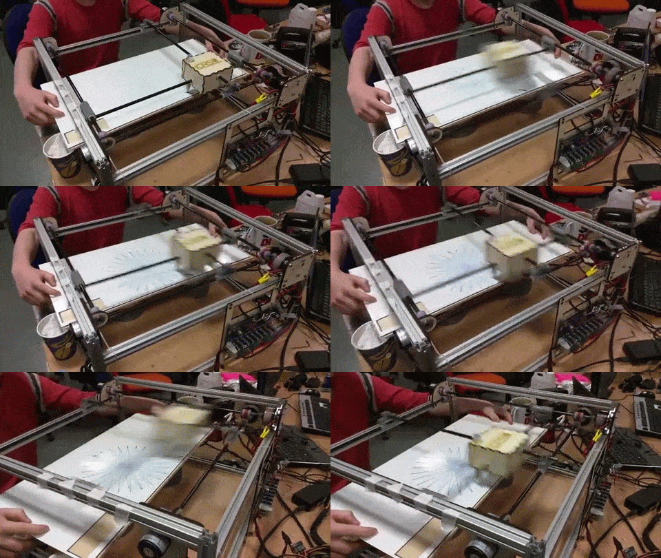
Like this:
This repository contains configuration and analysis scripts that runs on a PC. The other related repositories are:
- ODriveFirmware: Firmware that runs on the board.
- ODriveHardware: Circuit board design.
There is also ODriveFPGA, which contains the FPGA logic and software that runs on the FPGA based ODrive. This is not currently in development, but may be resumed at some later date.
Getting Started
References to hardware is with respect to v3.2. Other versions may still apply, but component designators may differ
It is perfectly fine, and even recommended, to start testing with just a single motor and encoder. Make sure you have a good mechanical connection between the encdoer and the motor, slip can cause disasterous oscillations. All non-power I/O is 3.3v output and 5v tolerant on input, except:
- GPIO_3 and GPIO_4 are NOT 5v tolerant on ODrive v3.2 and earlier.
You need one or two brushless motor(s), qudrature incremental encoder(s), and likely a power resistor. If you are powering from a battery that can absorb the energy from decellerating the load, and you wish to do regenerative breaking, then you do not need a power resistor. If your load is just the motor rotor, and you are testing at low speeds, it may not be required. If you are powering from a power supply, and have a load attached or are running at significant speeds/accelerations, you NEED to connect a power resistor. The power resistor values you need depends on your motor setup, and peak/average decelleration power. A good starting point would be a 0.47 ohm, 50W resistor.
Wire up the motor phases into the 3-phase screw terminal(s), and the power resistor to the AUX terminal. Wire up the power source (12-24V) to the DC terminal, make sure to pay attention to the polarity. Do not apply power just yet.
Wire up the encoder(s) to J4. The A,B phases are required, and the Z (index pulse) is optional. The A,B and Z lines have 1k pull up resistors, for use with open-drain encoder outputs. For single ended push-pull signals with weak drive current (<2mA), you may want to desolder the pull-ups.
The currently supported command modes are USB and step/direction.
- If you are sending commands over USB, you can plug in a USB cable on J1.
- If you are using step/direction, please see Setting up step/direction
You can now:
Startup procedure
The startup procedure is illustrated here. Note that the rotor must be allowed to rotate without any biased load during startup. That means mass and weak friction loads are fine, but gravity or spring loads are not okay. Also note that in the video, the motors spin after initalisation, but in the current software the default behaviour is to do position control to position 0, i.e. the position at startup.
Sending USB commands
Sending USB commands is documented here
Setting up Step/Direction
TODO
Getting help
If you have any issues or any questions please get in touch. The ODrive Community warmly welcomes you.