mirror of
https://github.com/odriverobotics/ODrive.git
synced 2026-09-17 03:18:59 +08:00

156 lines
6.7 KiB
Markdown
156 lines
6.7 KiB
Markdown
|
|
# Hoverboard motor and remote control setup guide
|
|
By popular request here follows a step-by-step guide on how to setup the ODrive to drive hoverboard motors using RC PWM input.
|
|
Each step is acompanied by some explanation so hopefully you can carry over some of the steps to other setups and configurations.
|
|
|
|
[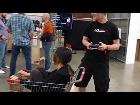](https://www.youtube.com/watch?v=ponx_U4xhoM) <br> Click above to play video.
|
|
|
|
### Hoverboard motor configuration
|
|
Standard 6.5 inch hoverboard hub motors have 30 permanent magnet poles, and thus 15 pole pairs. If you have a different motor you need to count the magnets or have a reliable datasheet for this information.
|
|
```txt
|
|
odrv0.axis0.motor.config.pole_pairs = 15
|
|
```
|
|
|
|
Hoverboard hub motors are quite high resistance compared to the hobby aircraft motors, so we want to use a bit higher voltage for the motor calibration, and set up the current sense gain to be more sensitive.
|
|
The motors are also fairly high inductance, so we need to reduce the bandwidth of the current controller from the default to keep it stable.
|
|
```txt
|
|
odrv0.axis0.motor.config.resistance_calib_max_voltage = 4
|
|
odrv0.axis0.motor.config.requested_current_range = 25 #Requires config save and reboot
|
|
odrv0.axis0.motor.set_current_control_bandwidth(100)
|
|
```
|
|
|
|
Set the encoder to hall mode (instead of incremental). See the [pinout](interfaces.md#hall-feedback-pinout) for instructions on how to plug in the hall feedback.
|
|
The hall feedback has 6 states for every pole pair in the motor. Since we have 15 pole pairs, we set the cpr to 15*6 = 90.
|
|
```txt
|
|
odrv0.axis0.encoder.config.mode = ENCODER_MODE_HALL
|
|
odrv0.axis0.encoder.config.cpr = 90
|
|
```
|
|
|
|
Since the hall feedback only has 90 counts per revolution, we want to reduce the velocity tracking bandwidth to get smoother velocity estimates.
|
|
We can also set these fairly modest gains that will be a bit sloppy but shouldn't shake your rig apart if it's built poorly. Make sure to tune the gains up when you have everything else working to a stiffness that is applicable to your application.
|
|
Lets also start in velocity control mode since that is probably what you want for a wheeled robot. Note that in velocity mode `pos_gain` isn't used but I have given you a recommended value anyway in case you wanted to run position control mode.
|
|
```txt
|
|
odrv0.axis0.encoder.config.bandwidth = 100
|
|
odrv0.axis0.controller.config.pos_gain = 1
|
|
odrv0.axis0.controller.config.vel_gain = 0.02
|
|
odrv0.axis0.controller.config.vel_limit = 1000
|
|
odrv0.axis0.controller.config.control_mode = CTRL_MODE_VELOCITY_CONTROL
|
|
```
|
|
|
|
In the next step we are going to start powering the motor and so we want to make sure that some of the above settings that requrie a reboot are applied first.
|
|
```txt
|
|
odrv0.save_configuration()
|
|
odrv0.reboot()
|
|
```
|
|
|
|
Make sure the motor is free to move, then activate the motor calibration.
|
|
```txt
|
|
odrv0.axis0.requested_state = AXIS_STATE_MOTOR_CALIBRATION
|
|
```
|
|
|
|
You can read out all the data pertaining to the motor:
|
|
```txt
|
|
odrv0.axis0.motor
|
|
```
|
|
|
|
Check to see that there is no error and that the phase resistance and inductance are reasonable. Here are the results I got:
|
|
```txt
|
|
error = 0x0000 (int)
|
|
phase_inductance = 0.00033594953129068017 (float)
|
|
phase_resistance = 0.1793474406003952 (float)
|
|
```
|
|
|
|
If all looks good then you can tell the ODrive that saving this calibration to presistent memory is OK:
|
|
```txt
|
|
odrv0.axis0.motor.config.pre_calibrated = True
|
|
```
|
|
|
|
Next step is to check the alignment between the motor and the hall sensor.
|
|
Because of this step you are allowed to plug the motor phases in random order and also the hall signals can be random. Just don't change it after calibration.
|
|
Make sure the motor is free to move and run:
|
|
```txt
|
|
odrv0.axis0.requested_state = AXIS_STATE_ENCODER_OFFSET_CALIBRATION
|
|
```
|
|
|
|
Check the status of the encoder object:
|
|
```txt
|
|
odrv0.axis0.encoder
|
|
```
|
|
|
|
Check that there are no errors. If your hall sensors has a standard timing angle then `offset_float` should be close to 0.5.
|
|
```txt
|
|
error = 0x0000 (int)
|
|
offset_float = 0.5126956701278687 (float)
|
|
```
|
|
|
|
If all looks good then you can tell the ODrive that saving this calibration to presistent memory is OK:
|
|
```txt
|
|
odrv0.axis0.encoder.config.pre_calibrated = True
|
|
```
|
|
|
|
OK, we are now done with the motor configuration! Time to save, reboot, and then test it.
|
|
The ODrive starts in idle (we will look at changing this later) so we can enable closed loop control.
|
|
```txt
|
|
odrv0.save_configuration()
|
|
odrv0.reboot()
|
|
odrv0.axis0.requested_state = AXIS_STATE_CLOSED_LOOP_CONTROL
|
|
odrv0.axis0.controller.vel_setpoint = 120
|
|
# Your motor should spin here
|
|
odrv0.axis0.controller.vel_setpoint = 0
|
|
odrv0.axis0.requested_state = AXIS_STATE_IDLE
|
|
```
|
|
|
|
Hopefully you got your motor to spin! Feel free to repeat all of the above for the other axis if appropriate.
|
|
|
|
### PWM input
|
|
If you want to drive your hoverboard wheels around with an RC remote contro you can use the [RC PWM input](interfaces.md#rc-pwm-input). There is more information in that link.
|
|
Lets use GPIO 3/4 for the velocity inputs so that we don't have to disable UART.
|
|
Then let's map the full stick range of these inputs to some suitable velocity setpoint range.
|
|
We also have to reboot to activate the PWM input.
|
|
```txt
|
|
odrv0.config.gpio3_pwm_mapping.min = -200
|
|
odrv0.config.gpio3_pwm_mapping.max = 200
|
|
odrv0.config.gpio3_pwm_mapping.endpoint = odrv0.axis0.controller._remote_attributes['vel_setpoint']
|
|
|
|
odrv0.config.gpio4_pwm_mapping.min = -200
|
|
odrv0.config.gpio4_pwm_mapping.max = 200
|
|
odrv0.config.gpio4_pwm_mapping.endpoint = odrv0.axis1.controller._remote_attributes['vel_setpoint']
|
|
|
|
odrv0.save_configuration()
|
|
odrv0.reboot()
|
|
```
|
|
|
|
Now we can check that the sticks are writing to the velocity setpoint. Move the stick, print `vel_setpoint`, move to a different position, check again.
|
|
```txt
|
|
In [1]: odrv0.axis1.controller.vel_setpoint
|
|
Out[1]: 0.1904754638671875
|
|
|
|
In [2]: odrv0.axis1.controller.vel_setpoint
|
|
Out[2]: 0.1904754638671875
|
|
|
|
In [3]: odrv0.axis1.controller.vel_setpoint
|
|
Out[3]: 28.152389526367188
|
|
|
|
In [4]: odrv0.axis1.controller.vel_setpoint
|
|
Out[4]: 61.21905517578125
|
|
|
|
In [5]: odrv0.axis1.controller.vel_setpoint
|
|
Out[5]: -52.990474700927734
|
|
```
|
|
|
|
Ok, now we should be able to turn on the drive and control the wheels!
|
|
```txt
|
|
odrv0.axis0.requested_state = AXIS_STATE_CLOSED_LOOP_CONTROL
|
|
odrv0.axis1.requested_state = AXIS_STATE_CLOSED_LOOP_CONTROL
|
|
```
|
|
|
|
### Automatic startup
|
|
Try to reboot and then activate AXIS_STATE_CLOSED_LOOP_CONTROL on both axis. Check that everything is operational and works as expected.
|
|
If so, you can now make the ODrive turn on the motor power automatically after booting. This is useful if you are going to be running the ODrive without a PC or other logic board.
|
|
```txt
|
|
odrv0.axis0.config.startup_closed_loop_control = True
|
|
odrv0.axis1.config.startup_closed_loop_control = True
|
|
odrv0.save_configuration()
|
|
odrv0.reboot()
|
|
```
|